
PT-020 and a Broken Bulkhead Connector
You are obviously at this page because you've either sheared the plastic section
of the bulkhead connector or you've broken one of the important pins in the
connector. If you fit in the former category, this page may be for you. If
you are in the later category you still have another choice....
I'm in the latter....what's my other choice?
Well, I'm guessing you've broken the pin when connecting the mike-dive bulkhead
adapter? If so, you are in good company. The pins are very fragile and easily
damaged. Michael does state this in the documentation he provides with his
solution. Personaly, I'd say this is a design flaw of the PT-020 and not of
Mike's solution.
Now the good news - only 3 of the pins are actually used. The other 2 are
redundant. If you look at the connector from above, with the camera port facing
away from you (as if you're taking a photo) the pins used are in the 5, 10
& 12 o'clock position. If you've broken the pins at either 2 or 7 o'clock
then you've no worries as they aren't used!
I've broken either the 5,10 or 12 o'clock pin, what else can I do?
You can always use the through housing infrared adapter that Matthias Heinrichs
produces. This couples the external flash to the camera using infrared beams.
I'm led to believe it's a little more fiddly to get set up and aligned properly,
but is very good in operation. Another alternative is to re-polarise the plug
and socket. This can be easily done by removing the plastic lugs in the socket.
You will then be able to rotate the TTL adaptor and the external connector
cable by a 5th of a turn so that the broken pin is effectively in an unused
position. Obviously, you will need to make new alignment marks for the internal
and external connectors but this is far from rocket science.
I've broken the red plastic bit. What can I do?
You have 4 choices....
1. plug the hole and use an IR. or digital slave adapter
2. buy a new housing
3. replace the bulkhead connector with something a bit more substantial
4. get a new bulkhead connector
Of the 4, option 4 is your best, but involves replacing some of the gear you've
already got.
Matthias Heinrich now produces replacement
Olympus bulkhead connectors which are also supplied with a replacement
Olympus TTL-C camera adaptor. This is by far the easiest option, but means
forking out another 180 euros.
OK, tell me about option 3
Very Important Notes:
1. This procedure is not reversible. Once you've cut the threads that's
pretty much it. But the, you're here becuase you've broken the bulkhead connector
right?
2. The page presented here is for replacing the bulkhead on the PT-020 housing
in conjunction with the Mike-dive wired strobe solution for Sea & Sea
strobes. I do not know if this will work with the Nikonos connector strobes
as I am not familiar with the number of wires / pins used on this range of
strobes.
Back to Option 3.....
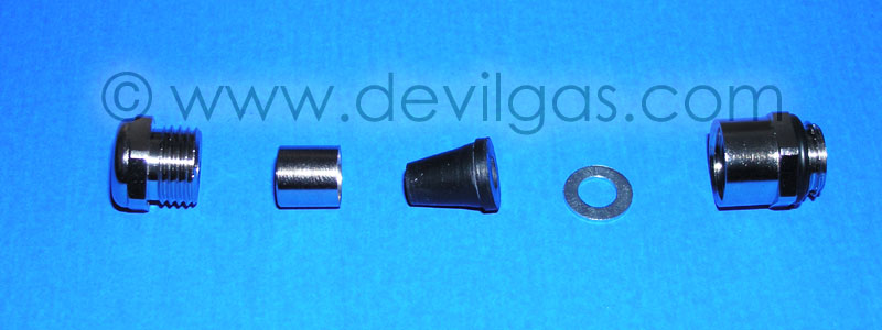
This is relatively straightforward to do as long as you have the correct bits
and pieces. The most important piece is the cable gland you require to allow
the cable to pass through the housing bulkhead into the camera. For this,
you will need a chromed cable gland rated to IP68 and has an M12 thread on
it. Both of the glands I obtained are M12x1.5 (the 1.5 being the thread pitch
which equates to 1.5mm between threads) and suitable for cables between 3
and 7mm in diamaeter. You can use a different thread pitch, but it is important
that the gland is M12 and will suit a 4mm cable.
In addition to the cable gland you will require some epoxy resin and a tap
to cut a thread on the housing. The tap needs to match the gland. In my case
I used a 12x1.5 tap (bought in a set from eBay for £10).
The gland can be a bit more troublesome to obtain. I got one from a local
electrical wholesale supplier, which would cost about £2.50. The other,
Michael was kind enough to send to me.
This one was the same as the ones he uses for the strobe connector block
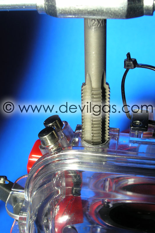
Cutting the thread
The reason we use the M12 gland is that to cut the required thread in the
housing means the existing bulkhead hole doesn't need to be altered. You simply
remove the broken Olympus connector in its entirety. Having never cut threads
in anything since my school days (20+ years ago) I was going to pracitce on
a spare piece of polycarbonate just to see if I was still as cack handed as
I was in school. In the end I couldn't be bothered and just attacked the housing.
As it stood, the housing was next to useless so the risk wasn't that great.
Cutting the thread is pretty straightforward. It's simply a case of turning
the die 1/8th of a turn at a time, working it back and forth a few times to
remove the excess material then turning a further 1/8. This may not be the
fastest or best method, but it worked for me and I didn't crack the housing.
In total it took about 5 mins to carefully cut the thread. The hardest part
is making sure the cut goes in absolutely vertical....a few practice runs
on spare plastic would be worthwhile if you've not done this before. Once
the thread is cut, carefully work the die back through the thread then clean
all the excess plastic shards away. To make things easier for me, I left the
housing closed, consequently lots of bits of plastic ended up trapped inside.
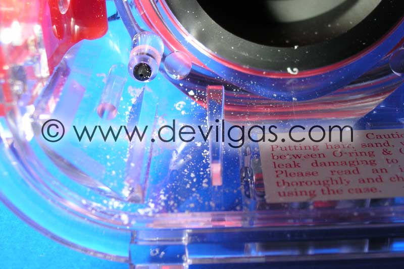
These, quite obviously, need to be carefully removed so as not to foul any
o-rings etc. You may find it is easier to have the housing open to avoid this
minor inconvenience.
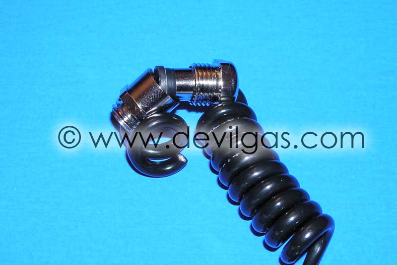
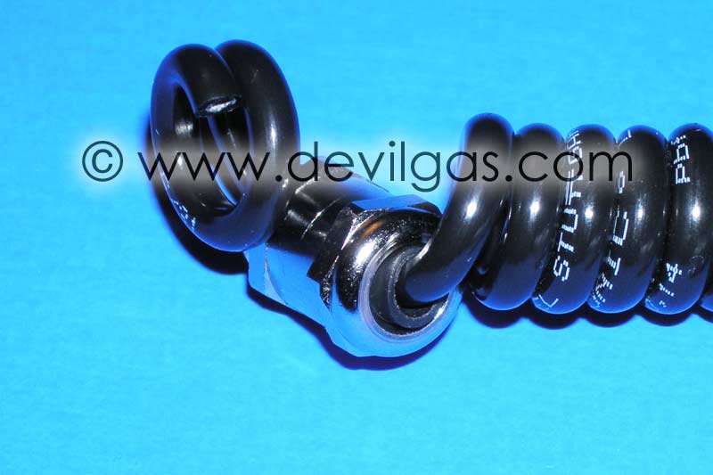
Inserting the gland
Once that is done, you can offer up the gland to check that it fits the newly
cut thread. The gland should have a sealing o-ring at it's base. This should
be removed as we will use epoxy resin to seal the thread to the housing. You
need to be able to screw the bulkhead connector in tight, but not so tight
that you strip your newly created thread. At this stage, you need to pluck
up the courage to cut through that nice strobe connector cable. You can either
cut directly through the Sea & Sea cable (not recommended) or cut through
the one that Michael supplied.
Now it's a case of threading the cable (after cleaning) through the gland,
leaving about 80-100mm of cable to play with, and tightening the gland as
tight as you can with spanners. It is important to do this now becuase when
the gland is epoxy'd to the housing, you won't be able to get a good grip
on the gland and risk breaking everything.
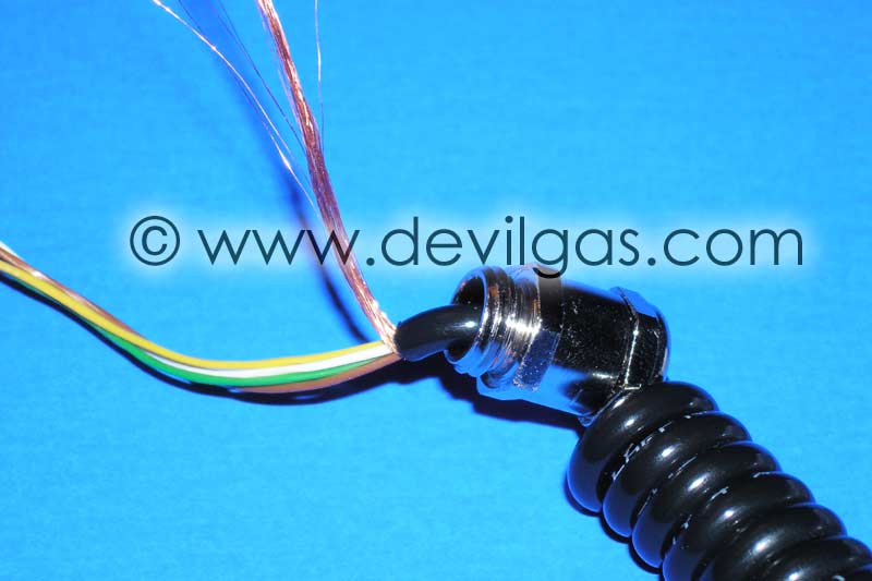
Now is a good time to prep the cable and strip the outer sheath as close to
the gland as you can.
It's probably not necessary, but I elected to fill the void with epoxy resin
as insurance against the IP68 seal, for whatever reason, failing.
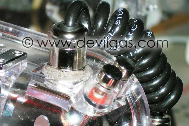
Finally, we load the entire thread of the gland with epoxy resin (no photo
of this as I was using Araldite Rapide which sets in a few minutes) and carefully
screw the gland into the housing as tight as you can by hand only. The resin
should overflow up and around the entire base of the gland.
If it hasn't, now may be a prudent time to build this area with resin whilst
it is still liquid. This will not only lock the gland in place but should
stop any water ingress as the thread should be completely flooded (and therefore
sealed) with epoxy resin.
Wiring the Cable to the TTL converter
Mike has been a star with this part as he has kept with a consistent colour
coding for the cables. What follows is certainly true for the Sea & Sea
connector, but will need verifying for the Nikonos plug. The colour coding
that Mike has used is as follows:-
White - Trigger
Brown - Ground
Green - TTL quench
Prior to knowing this, I sat down with a multimeter and mapped the entire
set of connections from the TTL adaptor to the strobe itself.
Starting at the TTL adaptor, there is a flat, 3 core cable that terminates
in the 5 sockets that plugged into the bulkhead on the inside of the housing.
These map directly to the 5 pins on the outside of the bulkhead. The pin at
12 o'clock is the trigger, the pin at 5 o'clock is ground and the pin at 10
o'clock is TTL quench. Working these back to the flat cable...the middle cable
is ground. The cable closest to the middle of the TTL adaptor that plugs into
the camera is the Trigger and the cable closest to the edge of the adaptor
is the TTL quench.
At this stage, you have 2 options. Either remove the small PCB that used to
connect to the internal bulkhead, or leave it there and push the wires from
mike-dive cable into the holes. I chose the latter after tinning the wires
with solder.
To cut a long story short, the White wire goes to the 12 o'clock hole, the
Brown wire goes to the 5 o'clock and the Green wire goes to the 7 o'clock.
With that done, just use a small cable tie to hold the wires in place and
go testing!
| v1 | 5th Oct 2004 | |
|
|
||