|
YS50TTL/s Surgery
Hacking / Converting a Sea and Sea YS50 TTL/S Strobe for use with an Olympus
5060Z and TTL adapter
First and foremost, nobody at devilgas photographic
will take any responsibility whatsoever for any damage caused to any equipment
or person as a result of following the text and/or images found upon this
page. We accept no responsibility for the content presented here. If you
are chimp enough to break anything you or somebody else owns because
you decided to follow what I've done, that is solely down to you.
Quite simply, you are responsible for your actions.
Opening the strobe unit may expose you to voltages in excess of 300v.
This can kill you.
If you are not comfortable with this, then please press the back button
now. If you electrocute yourself - which is very possible
with any flash unit - do not have your relatives, lawyers or friends come
running to blame us. As stated above, you are responsible for your
own safety.
Ok, now the necessary legal bit is squared away, down to business....
Unsurprisingly, this work is not original. It came about after seeing the, currently, German only version as presented by Matthias Heinrichs here
A bit of background..... For those using an Olympus 5060 in an
underwater housing and wanting to use an external flash, Matthias and
Mike Finger produce solutions that will work with the YS60 and above strobes.
My page on the 5060, the PT020 housing and the TTL adaptor can be found
here.
The YS50, with Sea and Sea connection as used on the Motormarine 2, is
not compatible as it cannot deliver 2 flashes in quick succession. The
modification on this page will overcome that shortfall and allow the strobe
to fire again within 100ms.
This modification is not needed for Nikon compatible strobe units (YS50
TTL/N).
What is presented here are my findings on attempting the modification.
Yet another warning and some basic safety tips.......
Read the 300v warning above?
There are 2 high voltage capacitors inside the strobe unit that store
upwards of 300v across their terminals. Touching these may very well kill
you, so some safety precautions need to be followed:-
• Never work on the opened strobe with the batteries
inserted
• Do not leave the opened strobe unit where others may touch it
• Do not even think about operating the strobe with the casing removed
• Do not short out the capacitors
OK, let's go hacking the strobe...... First off, we start by reducing
the possibility of electrocution from the capacitors. You will need a
paper clip and a set of batteries (preferably low on power so that the
capacitors take longer to charge)
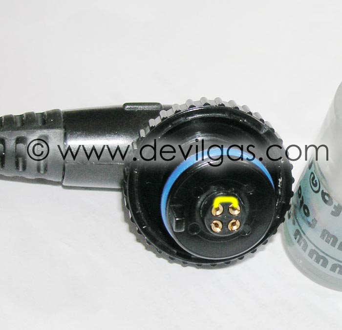
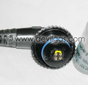
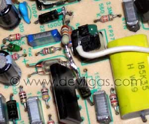
Switch the strobe on to the Full power setting and wait for the ready
light to come on. Short out the 2 sockets on the bulkhead connector (shown
below with the yellow line) and IMMEDIATELY switch off the strobe power.
This should prevent the capacitors charging too much.
Now, remove the batteries from the battery compartment.
You now need to locate the 3 screws that hold the 2 halves of the strobe
unit together. They are hidden under 3 yellow sticky plastic pads. You'll
need a small jeweller's cross head / Phillips screwdriver. The size 00
from the EF-S lens modify page
works well here also....
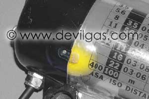
Remove all 3 and store them safely.
Remove or loosen the mounting bolt (the bolt that holds the strobe to
the lighting tray arm) and separate the 2 halves of the strobe unit. It
takes a bit of force the first time. Remove the O-ring and keep that safe
also.
Danger! The capacitors may still have
voltage across them. Treat the entire circuit board as being live and
potentially deadly to man or beast.
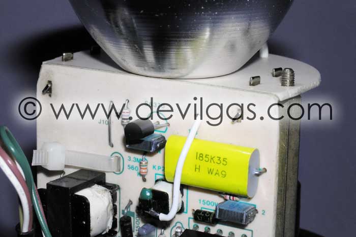
The smaller capacitor of the 2 is the yellow one shown here.

Use an insulated voltmeter to check the voltage across it's terminals.
It should be no greater than 20v. If the voltage is higher, it will need
to be discharged by connecting a 10k resistor across the terminals for
several minutes. Don't hold the resistor with un-insulated tools / hands
or you may successfully kill yourself. Why use a 10k resistor? Well, you
could just short the capacitors out of you like, but keep a fire extinguisher
handy as they may start to burn at the sudden short circuit discharge.
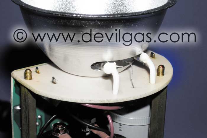
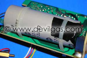
You'll need to repeat the same with the big capacitor on the rear of the
PCB. It has two fly leads - black and red. This is more difficult to discharge
as it requires greater care. It must however be done as you'll be playing
around with components connected directly to the red terminal.
In the best Haynes manual traditions, the image below shows the capacitor
after the PCB has been fully removed....
Once both capacitors are discharged / voltage is 20v or less across the
terminals (why 20v? it's a relatively safe voltage to work with....you'll
only feel a slight tingle if anything at all) you can remove the PCB from
the black part of the housing. The whole thing is held together with 2
long brass threaded hex stand-offs and a pair of nylon nuts. The nylon
nuts on mine broke when some post flood surgery was undertaken a few years
ago (the connector fractured allowing water to seep down the inside
of the the cable into the strobe unit)
The ends of the brass stand-offs are shown below:-

If the nylon nuts break you can either replace them with a suitable replacement
or just ignore them. The operation of the strobe doesn't appear to be
compromised with these missing.
With the nuts removed, you can finally remove the PCB from the housing
and get down to hacking the circuit board.
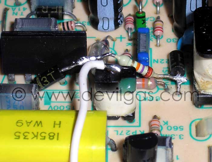
Basically, what is involved is to unsolder the anode from one diode (highlighted below in blue) on the circuit board, solder a 26k resistor to
the free end then solder the other end to the cathode (denoted by the band around the diode) of a nearby diode (highlighted below in red). The
resistor should be no more than 1/4 Watt
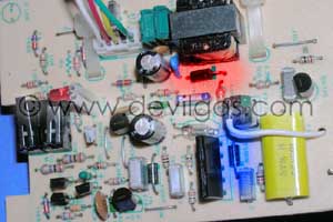
If your circuit board looks different to the above or the diodes are not
printed with "FR 3T 0.J" then I have no idea if the modification
will work.
When the 26k resistor has been soldered in place, it should look something
similar to this:-

The eagle eyed will see that the resistor I used was a 27k. That's all
I had in my spares box at the time.
If the strobe doesn't double flash, carefully reduce the value of the
resistor to no lower than 6k8. If the value is too low, the xenon tube
thyristor will stay on and entertain you with a smoke and flame show via
the new resistor. If your new resistor goes to resistor heaven because
the value was too low, try another with double the resistance of the failed
one e.g. 6k8 burns, try a 13k etc.
If the strobe doesn't double fire after that lot, then your YS50 can't
be converted. Simple as that.
Obviously, if you need to change the value of the resistor you need to
go through the entire discharge process again.
It is important to use a resistor with a max power dissipation of 1/4
watt. Anything higher and there is risk that other components may fail
instead of the newly added resistor.
Now it's time to bolt it all back together. Don't forget to clean the
o-ring and the mating surfaces and make sure no wires are trapped on re-assembly.
The 2 micro switches may need a bit of teasing to get them past the cammed
power switch, but other than that, there really is very little to it.
Personally, I did the entire modification in less than 30 minutes, including
taking photos etc.
After finally replacing the CR1225 3v battery in the TTL adaptor (anything
less than 2.7v and it won't fire the strobe), the YS50 was successfully
tested and double flashed as anticipated. This may not be a guaranteed
method (all I can say is that it worked for me) of getting a YS50TTL/s
strobe to work with the TTL adaptor, but it's certainly worth a try. Just
make sure you discharge those capacitors first!
Disclaimer
Neither myself, www.devilgas.com, my family, my friends, my pets or my vampire
squid take any responsibility whatsoever for any damage caused to anything
or anyone by duplicating what I've done. If you feel confident in not
destroying your expensive digital imaging equipment or not zapping yourself
with high voltage by trying this little ditty, that's your choice and not
mine.
| v1.4 |
9th Apr 2009 |
Updated link to Matthias' site |
| v1.3 |
11th Oct 2004 |
Testing results added |
| v1.2 |
4th Oct 2004 |
Note about why the capacitors shouldn't be shorted
out |
| v1.1 |
20th Sept 2004 |
Resistor values text updated. A big "thankyou" to
Matthias. |
| v1 |
16th Sept 2004 |
|
|
|
|